- Email: [email protected]
- Phone: (+86)13363300602

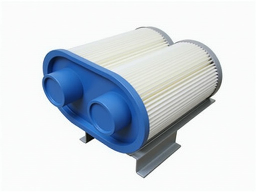
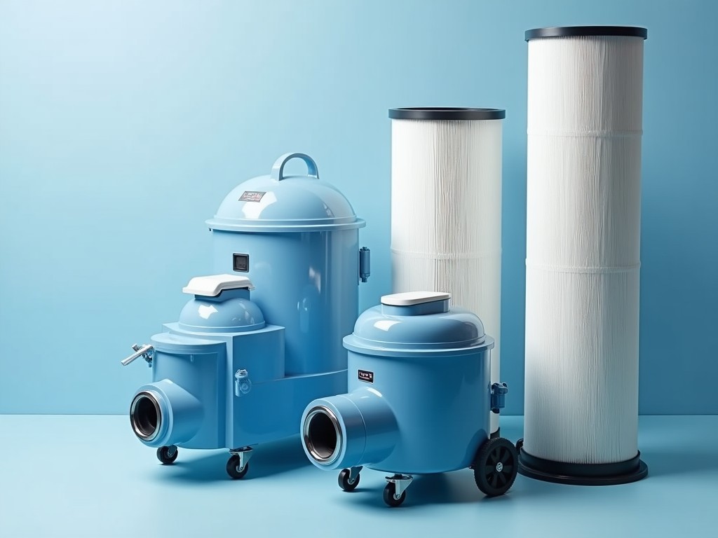
The cartridge geometry is defined by the required airflow volume and the turbine’s inlet pressure profile. A pleated media pack increases surface area while maintaining structural integrity under
Request a QuoteThe cartridge geometry is defined by the required airflow volume and the turbine’s inlet pressure profile. A pleated media pack increases surface area while maintaining structural integrity under cyclic loading.
Pleat height, spacing, and media thickness are selected to balance pressure drop against particulate capture efficiency. Typical pleat densities range from 5 to 8 pleats per inch, depending on the contaminant load.
End caps are molded from reinforced thermoplastic or metal alloys to provide a sealed interface with the turbine housing. Sealing surfaces are machined to a surface roughness of ≤0.8 µm to ensure leak‑tightness under operating pressures up to 2 bar gauge.
Media selection is driven by the expected particle size distribution, humidity levels, and any corrosive gases present in the intake air.
Filtration efficiency is expressed as the percentage of particles removed at a specified size, commonly measured per ISO 16890. For turbine inlet protection, efficiencies of 99.9 % at 5 µm are typical.
Initial pressure drop across a clean cartridge ranges from 150 to 300 Pa at the design flow rate, increasing predictably as dust loading accumulates.
Service life is estimated by the dust holding capacity, often quoted in grams of dust per square meter of media. Values between 200 g/m² and 500 g/m² are common for synthetic media in moderate‑dust environments.
Cartridges are designed for quick‑release clamping systems, allowing replacement without turbine shutdown when access doors are provided.
Monitoring differential pressure across the filter bank provides a reliable indicator of remaining service life; a rise of 50 % above the clean‑filter baseline typically signals the need for change‑out.
Proper handling avoids media deformation; cartridges should be stored flat and protected from direct UV exposure prior to installation.
Gas turbine power plants require inlet filtration to protect compressor blades from erosion and fouling, directly influencing heat rate and maintenance intervals.
Oil and gas offshore platforms use corrosion‑resistant media to withstand salt‑laden air and occasional hydrocarbon vapors.
Industrial cogeneration units benefit from low‑pressure‑drop designs that minimize parasitic power loss while meeting stringent emission standards.
Cartridge length, diameter, and end‑cap configuration can be adapted to match existing housing dimensions or to optimize flow distribution.
Media grade, pleat geometry, and sealing material are selected based on client‑provided environmental data such as temperature extremes, humidity, and contaminant composition.
Optional features include anti‑static coatings, hydrophobic treatments, and integrated pressure‑tap ports for online monitoring.
Each cartridge undergoes dimensional verification of pleat height, end‑cap squareness, and overall length using calibrated CMM equipment with a tolerance of ±0.2 mm.
Media integrity is checked by bubble point testing to confirm pore size distribution and by tensile strength measurements to ensure durability under handling.
Final inspection includes a pressure‑drop measurement at the rated flow rate; units deviating more than ±10 % from the target are segregated for review.
| Parameter | Typical Value | Unit | Notes |
|---|---|---|---|
| Filtration Efficiency @ 5 µm | ≥99.9 | % | ISO 16890 test method |
| Initial Pressure Drop | 150‑300 | Pa | At design flow rate |
| Dust Holding Capacity | 200‑500 | g/m² | Dependent on media type |
| Operating Temperature Range | -20 to 250 | °C | Media dependent |
| End‑Cap Seal Leak Rate | ≤0.01 | bar·L/min | Measured at 1.5 bar differential |
Yes. Cartridge length, outer diameter, and end‑cap flange patterns are adjusted to match the specific turbine housing interface supplied by the client.
Required data include design airflow (Nm³/h), inlet pressure and temperature, expected particulate size distribution, humidity levels, and any corrosive gas concentrations.
Standard offerings are synthetic fiber blends, glass‑fiber media, and metal‑mesh substrates. Specialty coatings can be applied upon request.
Each unit undergoes dimensional verification, media integrity testing (bubble point and tensile strength), and final pressure‑drop validation at rated flow.
Cartridges are packed in corrugated boxes with internal foam dividers; for export, heat‑sealed polyethylene bags and palletized crates provide moisture and impact protection.
To discuss your specific inlet filtration requirements or to request a technical datasheet, please use the contact form below.
Submit InquiryCopyright © 2026 www.chinacartridgefilter.com All Rights Reserved.