- Email: [email protected]
- Phone: (+86)13363300602

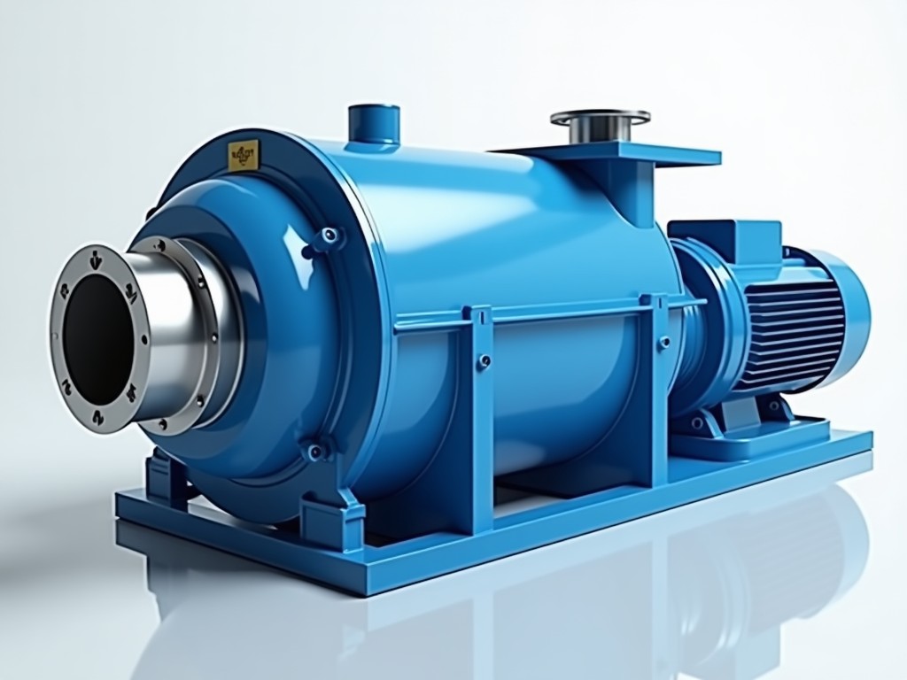
Self‑cleaning air filters address the continuous particulate loading that gas turbine compressors experience in harsh environments. By automatically removing captured dust, the filter maintains a
Request a QuoteSelf‑cleaning air filters address the continuous particulate loading that gas turbine compressors experience in harsh environments. By automatically removing captured dust, the filter maintains a stable pressure drop and protects downstream blades from erosion. This section explains the underlying mechanics, design variables, and performance considerations that influence selection.
The filter element consists of a pleated media pack housed in a cylindrical cartridge. During normal operation, airflow passes radially outward through the media, trapping particles on the upstream face. A pulsed‑jet cleaning system directs short bursts of compressed air downstream, dislodging the collected cake and allowing it to fall into a hopper for disposal.
Cleaning cycles are triggered by a differential pressure sensor that monitors the drop across the filter. When the setpoint is reached—typically 250 Pa to 350 Pa depending on inlet conditions—the control valve opens for a prescribed duration, usually 100 ms to 200 ms per pulse. This approach restores the initial pressure drop without shutting down the turbine.
| Parameter | Range / Typical Value | Notes |
|---|---|---|
| Filter media type | Synthetic polyester, fiberglass blend | Chosen based on temperature tolerance and chemical resistance |
| Maximum operating temperature | 250 °C (continuous) | Limited by binder stability; higher grades available on request |
| Cleaning pressure (pulse air) | 0.5 MPa to 0.8 MPa | Regulated via solenoid valve; consumption < 0.2 Nm³ per cleaning event |
| Cartridge length | 300 mm to 1200 mm | Determined by required dust holding capacity and installation envelope |
| Expected service interval | 3 months to 12 months | Dependent on inlet dust concentration; monitored via pressure drop trend |
The filter housing is fabricated from sheet metal with continuous weld seams to prevent leakage under pressure differentials. Flange interfaces use ANSI B16.5 Class 150 compatible surfaces, allowing bolt‑on mating to turbine inlet ducts. Gaskets are typically spiral‑wound graphite with stainless steel inner rings for temperature resilience.
Media pleats are bonded to a perforated metal support core that provides structural rigidity during pulse‑jet impingement. The core material matches the housing specification to avoid galvanic corrosion. End caps incorporate quick‑release clamps for cartridge removal without specialized tools, supporting maintenance intervals under 30 minutes.
Gas turbine installations in desert climates often encounter sand loading exceeding 0.5 g/m³. In these conditions, a self‑cleaning filter reduces the frequency of manual shutdowns, translating to increased annual availability by an estimated 2 % to 4 % based on OEM field data. The pressure drop stability also helps maintain compressor efficiency, limiting specific fuel consumption growth.
Offshore platforms face saline aerosol and occasional hydrocarbon mist. For such environments, the filter media can be treated with a hydrophobic coating, and the housing constructed from 316L stainless steel to resist pitting. These adaptations extend the useful life of the filter beyond the typical 12‑month interval observed in dry, inland sites.
Each cartridge undergoes a bubble point test to verify media integrity, ensuring that the largest pore does not exceed the specification for the target particle size. Dimensional checks are performed on housing critical features—flange flatness, bolt hole pitch, and cartridge length—using calibrated CMM equipment with a tolerance of ±0.2 mm.
Pulse‑jet nozzles are flow‑tested to confirm uniform distribution; variation between nozzles is kept below 5 % to avoid localized media wear. Final assembly includes a pressure decay test at 1.5 times the design differential pressure to validate seal effectiveness. Documentation of these tests accompanies every shipment.
Yes. Cartridge diameter, length, and flange pattern are adjusted to match the existing inlet duct or to meet specific installation constraints. Detailed drawings are provided upon request after reviewing the host equipment specifications.
Required data include inlet airflow rate (kg/s), temperature range, expected dust concentration and composition, available cleaning pressure, and any space limitations for housing installation. Providing this information enables accurate sizing of media area and pulse‑jet parameters.
Inspection comprises media bubble point testing, housing dimensional verification, nozzle flow uniformity, and pressure decay validation as described in the Quality Assurance section. Test certificates are included with each delivery.
Cartridges are packed in double‑wall corrugated boxes with internal foam spacers to prevent movement. For export, pallets are shrink‑wrapped and fitted with corner protectors; moisture‑barrier liners are added for humid climates.
Copyright © 2026 www.chinacartridgefilter.com All Rights Reserved.